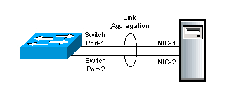
Modern servers usually have multiple ethernet interfaces, and by combining them into an LACP trunk, you can pass VLAN’s over then to extend the amount of traffic over a bonded network link.
Converting a Linux CENTOS server with 2 or more Ethernet interfaces to an LACP bonded network link couldn’t be simpler. The process is well documented and its been stable for years. Adding support for VLANs so all traffic leaves the server via the LACP trunk and ends up in the correct VLAN is very simple to implement and is also highly reliable.
Follow the step below and it should work first go.
Step 0 – Backup!
First, make a backup of ALL your ifcfg-xxxx files in /etc/sysconfig/network-scripts/ directory.
Mine originally looked like:
-rw-r–r– 1 root root 324 Aug 18 03:32 ifcfg-em1
-rw-r–r– 1 root root 250 Oct 14 13:09 ifcfg-em2
-rw-r–r– 1 root root 254 Apr 10 2015 ifcfg-lo
-rw-r–r– 1 root root 44 Aug 31 23:00 ifcfg-venet0
I copied mine to the /root directory to make sure I have clean working backups. If anything goes wrong, you should be able to (from the console), replace the modified ones back and reboot back into a working system if needed. Make sure you have a working console first!.
Step 1 – Enable bonding
I will use bond0 to identify the LACP bond that I will create. First, create a bonding.conf file in /etc/modprobe.d/.
The file contents are a single line:
[root@demo ~]# cat /etc/modprobe.d/bonding.conf
alias bond0 bonding
[root@demo ~]#
Step 2 – Create the bond slaves
The bond slaves are the actual Ethernet interface ports, they might be identified as eth0, eth1 etc but in my case on the Dell servers I was looking after they come up as em1 and em2
The em1 and em2 devices are defined as ifcf-em1 and ifcfg-em2 files and live in /etc/sysconfig/network-scripts/
Create the file ifcfg-em1 first and enter the following:
DEVICE=”em1″
BOOTPROTO=”none”
NM_CONTROLLED=”no”
TYPE=”Ethernet”
ONBOOT=”yes”
MASTER=bond0
SLAVE=yes
USERCTL=no
HWADDR=<MAC Address Here>
This file tells the network driver that they are a SLAVE, the MASTER is bond0 and the hardware address to bind to as well as to activate on boot.
For YOUR implementation, change the DEVICE and HWADDR to suit your hardware. The ifcfg-em2 file is identical except for the DEVICE and HWADDR values.
Step 3 – Bond0 master
The bond master file is ifcfg-bond0, it defines the LACP bond, so the LACP parameters and IP address are defined as shown below:
DEVICE=bond0
ONBOOT=yes
BOOTPROTO=none
IPV6INIT=no
USERCTL=no
BONDING_OPTS=”mode=4 xmit_hash_policy=2 miimon=300 downdelay=300 updelay=300″
NAME=”MasterBond0″
NM_CONTROLLED=no
IPADDR=<IP address of BOND>
PREFIX=24
Note: the page wrap has forced the ‘updelay’ to appear on a new line but it is actually part of the “BONDING_OPTS” line.
bond0 will be activated prior to the VLAN files.
Step 4 – VLAN’s bonded to bond0
The only significant difference between a bond master definition and a VLAN is the lack of the BONDING_OPTS line and the addition of the VLAN=yes line.
Also note, the file name contains the VLAN ID at the end so everything lines up.
For each network that is in a unique VLAN you want the server to access, define a file like the one shown below and change the DEVICE and IPADDR details as required.
For VLAN 100, (file: ifcfg-bond0.100) with IP traffic in the 192.168.100.0/24 range:
DEVICE=bond0.100
ONBOOT=yes
BOOTPROTO=none
IPV6INIT=no
USERCTL=no
NAME=”PrivateNet”
NM_CONTROLLED=no
IPADDR=192.168.100.10
PREFIX=24
VLAN=yes
For VLAN 20, (file: ifcfg-bond0.20) with IP traffic in the 192.168.20.0/24 range:
DEVICE=bond0.20
ONBOOT=yes
BOOTPROTO=none
IPV6INIT=no
USERCTL=no
NAME=”AppServerNet”
NM_CONTROLLED=no
IPADDR=192.168.20.10
PREFIX=24
VLAN=yes
Continue to define a ifcfg-bond0.XXXX file for each network.
After adding the VLAN definition files, my directory looked like:
ls -la /etc/sysconfig/network-scripts/
-rw-r–r– 1 root root 204 Dec 9 14:42 ifcfg-bond0
-rw-r–r– 1 root root 236 Dec 9 14:42 ifcfg-bond0.20
-rw-r–r– 1 root root 239 Dec 9 14:43 ifcfg-bond0.100
-rw-r–r– 1 root root 325 Dec 9 14:43 ifcfg-bond0.200
-rw-r–r– 1 root root 137 Dec 9 14:45 ifcfg-em1
-rw-r–r– 1 root root 137 Dec 9 14:45 ifcfg-em2
Step-5 – Rename and Reboot!
For a major change like implementing Bonding, a reboot will be required so the bonding Kernel modules are loaded and the new interfaces take effect.
Doing a service network restart will not work in this case.
Checking the bond
The bond will appear in both an ifconfig output as well as in /proc/net/bonding.
For each bonded master there will be a file present with the status of the bond. If you have bond0 and bond1 then there will be two (2) files present.
Here is a sample of my LACP trunk taken from a live system:
cat /proc/net/bonding/bond0
Ethernet Channel Bonding Driver: v3.7.1 (April 27, 2011)
Bonding Mode: IEEE 802.3ad Dynamic link aggregation
Transmit Hash Policy: layer3+4 (1)
MII Status: up
MII Polling Interval (ms): 300
Up Delay (ms): 300
Down Delay (ms): 300
802.3ad info
LACP rate: slow
Min links: 0
Aggregator selection policy (ad_select): stable
Active Aggregator Info:
Aggregator ID: 1
Number of ports: 2
Actor Key: 33
Partner Key: 3
Partner Mac Address: f4:31:50:66:aa:01
Slave Interface: em2
MII Status: up
Speed: 10000 Mbps
Duplex: full
Link Failure Count: 0
Permanent HW addr: d0:44:ee:47:55:cc
Aggregator ID: 1
Slave queue ID: 0
If you down an interface the file should then show a single interface as “UP”.
If it goes pear shape?
Access the console, rename the bond files (I put an “x-” in front of the names) and copy the backup copies back in place.
Then reboot again to get back to your original configuration and double check your bonding config (line by line looking for a TYPO).
-oOo-