Overview
Infiniband is primarily used in High Performance Computing (HPC) and provides a very fast network interconnect with an incredibly small latency. One of the most common topologies implented is the “Fat Tree” layout. The fat tree topology has host nodes connected at the end points of the network via PCI Infiniband cards.
The Infiniband Iterface cards implement Remote Direct Memory Access (RDMA) which allows the cards to place data directly into the memory of the end node so that no Kernel intervention is required.
When we took on our HPC Re-engineering Contract we were exposed to FDR Infiniband from Mellanox which was already old technology and in much need of an upgrade. Since FDR was released it’s been replaced with EDR (100GBs) and that has been replaced with HDR (200GBs).
Topology Overview
There are lots of different topologies available for connecting High Performance Compute nodes. A Fat Tree Network topology consist of Master Switches and Leaf Switches. Servers, Storage and other “End Nodes” connect to the Leaf Switches. There are no Master to Master links and no Leaf to Leaf links. All up links pass through a Master.
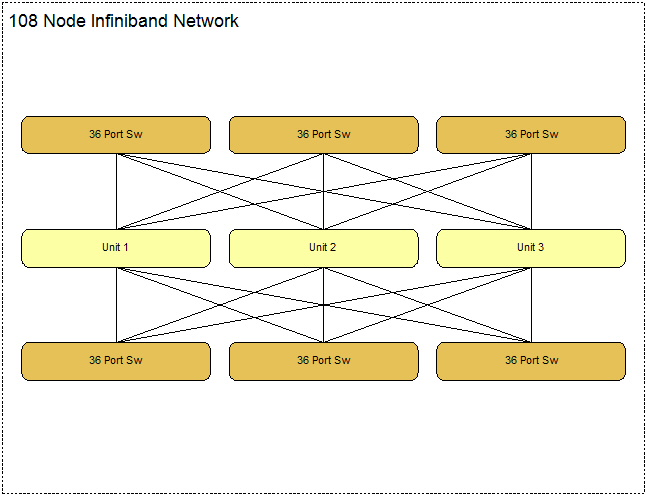
108 Node Configuration
For Non-Blocking operation (which is best to have), a 108 node configuration has 6 Leaf Switches and 3 Master Switches.
With Non-Blocking Modes half the Leaf Switch ports are define as up links, so 18 ports are used to connect to end nodes. The first 18 ports consist of 3 groups of six ports (3 masters so 3 groups).
In a blocking design, the up link count is less than the node count per switch so more end nodes can be connected.
Connecting Hosts
Hosts connect to a leaf switch, with 18 uplinks, that leaves 18 hosts per switch, hence 108 hosts across 6 switches.
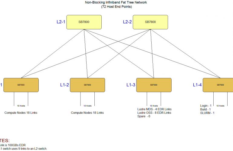
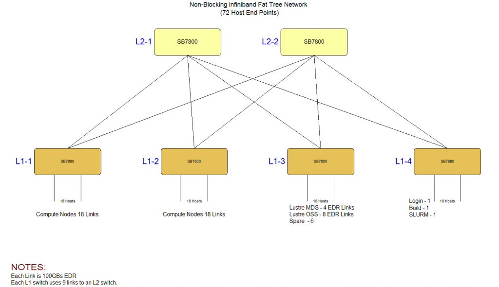
72 Node Configuration
With a 108 node (non-blocking) configuration needing 9 switches, a smaller 72 node network can be built with 6 switches.
The 72 node non-blocking configuration requires 2 Master Switches and 4 Leaf Switches, like the larger designs, the first 18 ports are defined as up links. As there are 2 masters then 9 links go to each master.
This article has primarily focused on non-blocking modes in order to achieve high performance operation. It is possible to move to less up links and hence free up ports for more end nodes. So ratios of 2:1 or more are available.
Visit the Melanox Web Site to obtain more information on alternate topolgies.
-oOo-